Pages

Ads 468x60px

Labels

Text Widget

Recent Posts

Download

Showing posts with label EEE Miniprojects. Show all posts

Monday, 12 March 2012

Fire alarm using thermistor & NE555

Fire alarm using thermistor & NE555

Description.
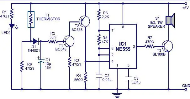
Many fire alarm circuits are presented here,but this time a new circuit using a thermistor and a timer to do the trick. The circuit is as simple and straight forward so that, it can be easily implemented. The thermistor offers a low resistance at high temperature and high resistance at low temperature. This phenomenon is employed here for sensing the fire.
The IC1 (NE555) is configured as a free running oscillator at audio frequency. The transistors T1 and T2 drive IC1. The output (pin 3) of IC1 is couples to base of transistor T3 (SL100), which drives the speaker to generate alarm sound. The frequency of NE555 depends on the values of resistances R5 and R6 and capacitance C2. When thermistor becomes hot, it gives a low-resistance path for the positive voltage to the base of transistor T1 through diode D1 and resistance R2. Capacitor C1 charges up to the positive supply voltage and increases the the time for which the alarm is ON. The larger the value of C1, the larger the positive bias applied to the base of transistor T1 (BC548). As the collector of T1 is coupled to the base of transistor T2, the transistor T2 provides a positive voltage to pin 4 (reset) of IC1 (NE555). Resistor R4 is selected s0 that NE555 keeps inactive in the absence of the positive voltage. Diode D1 stops discharging of capacitor C1 when the thermistor is in connection with the positive supply voltage cools out and provides a high resistance path. It also inhibits the forward biasing of transistor T1.
Circuit diagram with Parts list.
fire-alarm-circuit.jpg
Notes.
  • The circuit can be powered from a 6V battery or a 6V power supply.
  • Click Here ! for the circuit diagram of a power supply circuit for this project.
  • The thermistor can be mounted on a heat resistant material like mica to prevent it from damage due to excessive heat.
  • The LED acts as an indication when the power supply is switched ON.

Contact Lenses with “The Terminator” Mode!!


Special Contact Lens
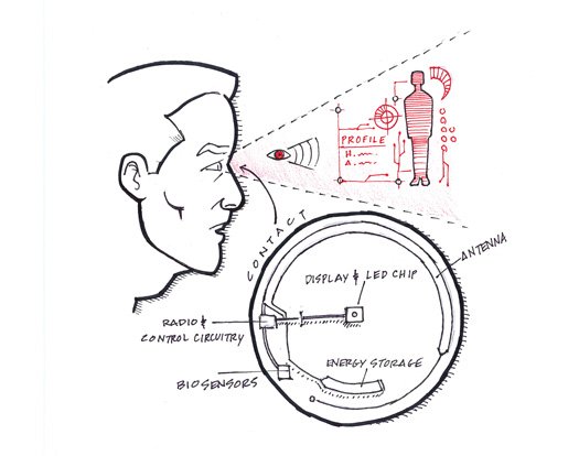
In the movie “The Terminator”, we see Arnold Schwarzenegger check out the complete profile of the subject he is about to face.  A similar technology has been developed by Babak Parviz, an electrical engineer at the University of Washington.
Babak designed a lens that can be used to display a single pixel at a time. This display can be switched on and turned off through a wireless medium. The lens consists of an IC which stores the energy, along with an LED that shoots the light towards the eyes. But, the lens is not capable of intercepting objects that are very close to the eye. This problem is overcome by placing some counter lenses in between the LED and the eye. The same principle can be simply tested by placing an appropriate magnifying glass to see your finger that is placed very near to your eye.
Till now, the lens has only been designed to display one pixel. But, there may be a time when you could use the lenses to bring together all the displays you interact with on a daily basis – your PC, fridge, chair, mobile – into one personal display in your eye. Later, the same technology could be modified to bring in virtual images into the real world. For example, you could design the interior of your plain room with paintings, furniture and so on.
As show in the figure above, the LED part of the lens is opaque, but these little dark spots shouldn’t make the images unnoticed. A control circuit and a radio are also shown. They are used to gather the energy from a transmitter kept at the edge of the lens and convey the information to the outside. The design is made sleek enough in such a way that they do not block the view in any way. The lens was first tested on animals and they have proved to be working perfectly without any safety problems. The officials are waiting for an approval to test it on humans.
If this technology does become famous, the researchers will have to take special care in protection of the software side. That is, someone could easily pop up spams inside the control circuitry of the lens and block the view of a person, who may be busy driving his car.

Wednesday, 22 February 2012

Wireless mains voltage tester.


Description.
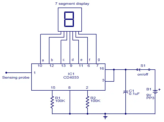
This circuit can be used to test whether mains voltage is present or not without having electric contact with mains line. The CMOS IC CD4033 is the heart of this circuit. The CD4033 consists of a 5 stage decade Johnson counter and an output decoder for converting the Johnson code to a 7 segment decoded output for driving 7 segment LED display. A 10cm long insulated copper wire connected to the clock pin (pin1) of the IC serves as the sensor. The sensor wire has to be placed in the vicinity of the mains wire to be tested. When there is no voltage in the mains line, no voltage will be induced in the sensor wire and the display will show a random digit. When there is voltage in the mains line, a small voltage will be induced in the sensor wire due to electromagnetic induction and this voltage is sufficient enough to clock the CMOS IC CD4033. Now the display will count from zero to nine and repeat.
Circuit diagram.
wireless mains indicator
Notes.
  • The circuit can be assembled on a Vero board.
  • Use 9V PP3 battery for powering the circuit.
  • Use a 10cm insulated wire as the sensor.
  • The IC must be mounted on a holder.
  • Switch S1 can be a miniature ON/OFF switch.

Stereo headphone amplifier


LM4910 stereo headphone amplifier.

LM4910 belonging to the Boomer series of National Semiconductors is an integrated stereo amplifier primarily intended for stereo headphone applications. The IC can be operated from 3.3V ans its can deliver 0.35mW output power into a 32 ohm load. The LM4910 has very low distortion ( less than 1%)   and the shutdown current is less than 1uA. This low shut down current makes it suitable for battery operated applications. The IC is so designed that there is no need of the output coupling capacitors, half supply by-pass capacitors and bootstrap capacitors. Other features of the IC are   turn ON/OFF click elimination, externally programmable gain etc.
                          Circuit diagram of the LM4910  stereo headphone amplifier is shown above.C1 and C2 are the input DC decoupling capacitors for the left and right input channels. R1 and R2 are the respective input resistors. R3 is the feed back resistor for left channel while R4 is the feed back resistor for the right channel. C3 is the power supply filter capacitor. The feedback resistors also sets the closed loop gain in conjunction with the corresponding input resistors.

Notes.

  • The IC is available only  in SMD packages and care must be taken while soldering.
  • The circuit can be powered from anything between 2.2V to 5V DC.
  • The load can be a 32 ohm headphone.
  • Absolute maximum supply voltage is 6V  and anything above it will destroy the IC.
  • A logic low voltage at the shutdown pins shut downs the IC and a logic high voltage at the same pin activates the IC.

Saturday, 18 February 2012

Simple Sound Generator Circuit


Description

This is a real scream generator circuit suitable for any purpose like alarm or car horn.The circuit is based on two transistors Q1 and Q2.When you press the switch S2 the siren starts up moving to a high frequency.When the switch is released the tone slips down until you shift it up again by pushing the switch S2.

Sound Generator Circuit Diagram with Parts List.


Notes.

  • Adjustment of tone quality can be obtained by different values for C2.
  • If the alarm oscillates before S2 is pressed.The transistor is leaky, replace it.
  • S1 can be used as a power switch.
 

Sample text

Sample Text

Sample Text