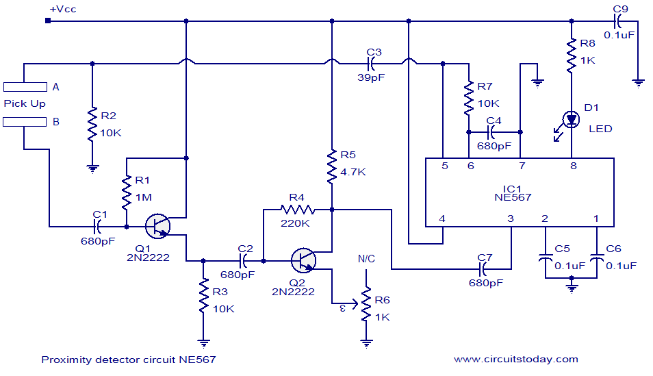
CIRCUIT DIAGRAM:

A simple proximity detector circuit using NE567 is shown here. Pin 8 is the output terminal of the internal output driver circuit inside the IC. This pin goes low when the input frequency to the IC (at pin3) is with in the detection band. Resistor R7 and capacitor C4 sets the frequency of oscillations. These oscillations are available at pin 5 and it is coupled to the terminal A of the pick up assembly using capacitor C3. Terminal B picks up the oscillations and couples it to the base of the transistor Q1 through capacitor C1. Q1 and Q2 forms a two stage collector to base biased 2 stage amplifier. R1 and R4 are the collector to base biasing resistors for Q1 and Q2. C2 couples the output of first stage to the second stage. The picked up signal is thus amplified and applied to the input pin (pin3) of the IC through capacitor C7. C6 forms the output filter capacitor and capacitor C5 determines the band width of the receiving signal. C9 is a power supply by pass capacitor. C2 and R2 provides a phase shift to the VCO signal from the IC and this phase shifted signal is detected by the IC. When some object comes near the pick up assembly, the capacitance between its terminals change. This change in capacitance changes the frequency ,IC detects this change and shows the indication. Resistor R8 limits the output LED current.
Notes.
- Use 9V DC for powering the circuit.
- If you are using an AC adapter, then it must be well regulated and free from noise.
- The pick up assembly can be made using two metal strips.
- POT R6 can be used for adjusting the sensitivity.


0 comments:
Post a Comment